Coil Tester

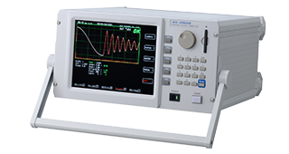
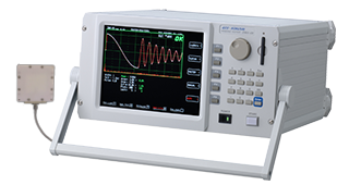
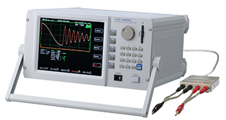
Impulse Winding Tester DWX-LI Series

DWX-300LI3a, DWX-01LI3a

High-Speed Testing for Ultra-Low-Inductance Coils!
Apply 180 V or more to 100 nH and test at 10 ms per pulse!

Impulse voltage can be applied to the coils of chip power inductors to perform insulation testing between windings (surge testing).

For Evaluation Testing: Suitable for detailed evaluation testing of coil components.
For High-Speed Inspection Equipment: Test time: 10 ms without judgment and 18 ms with judgment.

※ (Fastest conditions: air-core coil, one impulse, no judgment, and no screen display)

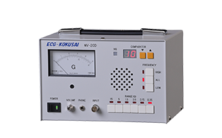
Power Inductor DWX300 Image

Features

  • A model specialized for insulation testing inside the coils of metal-type chip power inductors.
  • The 4-terminal test circuit enables sufficient high-voltage application to ultra-low-inductance coils.
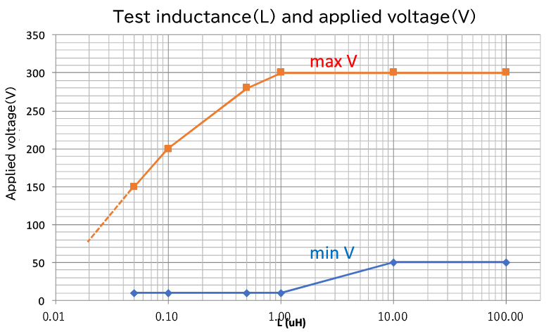
    For a 100 nH coil, a voltage of 180 V or higher (displayed value) can be applied.
  • The 12-bit voltage resolution and 300 MHz waveform sampling enable detailed response waveforms to be displayed.
  • This single unit is equipped with three functions: “High-Speed Mode,” ideal for high-speed inspection equipment and coil internal insulation testing; “Test Mode,” for pass/fail judgment; and “Breakdown Test Mode,” for detailed evaluation.
  • With one pulse applied without judgment, the minimum test time is 10 ms, enabling high-speed operation suitable for use on mass-production lines.

Overview

[Maximum Applied Voltage Range (Target Values) Graph]


[Options]

● Manual Fixture
  • DWX-01LI-OP1
  • DWX-01LI-OP2A-M

● Various Test Cables
・4-terminal box-type cable ・SMA cable for handler equipment ・BNC cable for handler equipment
Please contact us for details.

Performance Comparison

 DWX-300LI3a DWX-01LI3a DWX-05A
Applications Precision Testing Ultra-Low Inductance General Coil Components
Inductance Range L-LO: 0.01μH~1μH  L-HI: 1μH~100μH  Two-Range Switching 10μH~100mH
Maximum Output Voltage (No Load) 300V 1000V 5000V
Measurement Voltage Resolution 0.1V step 0.3V step 100V step
Maximum Applied Voltage (Approx.) See the “Maximum Applied Voltage Range (Target Values)” Graph 1,000 V at 10 μH
Waveform Sampling Resolution 300MHz・3.333nsec 12bit 100MHz
Minimum Test Time (1 Pulse, No Screen Display) High-Speed Mode: With judgment: 18 ms Without judgment: 10 ms
Tester Mode: With screen display: 108 ms Without screen display: 53 ms
200msec
Judgment Items / Output Signal (When the option is installed) [Standard Judgment Items]
• Test judgment: OK / NG
• Area: NG
• Waveform Difference Area (Dif Area): NG
• Peak Voltage Variation (PeakStb): NG
• Laplacian: NG
• Attenuation Rate (Qatt): NG
• Contact Check (PreCheck): CE

[Option: Individual I/O Output for Each Judgment Item]
For each of the above judgment items (Area, Dif Area, PeakStb, Laplacian, and Qatt), the judgment result (NG) can be individually output to external equipment as an I/O signal.
Area (Area%)
・Waveform Difference Area (Dif Area%)
・Peak Voltage (Peak Stb%)
・Discharge Level (Laplacian)
・Waveform Attenuation Rate (Laplacian%)
・Breakdown Voltage Evaluation Test (BDV) / Manual Withstand Voltage Evaluation Test (Manual BDV)
Test Circuit 4-Terminal 2-Terminal
Test Cable Length Range Recommended: 1.6 m
Compatible with Partial Discharge Testing Not Supported PD-Compatible
Additional Functions Master waveform storage capacity: 196 models; expandable via CF memory card; external control via RS-232C and I/O; test result log storage and screen hard-copy storage
External I/O Control Signals Application Trigger (Trig), Application End (Index), etc.
Supports high-speed interface timing for inspection handlers.
External control via signals such as Test Start (Start) and Test in Progress (Busy)
External Dimensions
(excluding the carry handle)
345(W)×185(H)×360(D)
Accessories 4-Terminal Test Cable (Length to Be Discussed Separately) 2-Terminal Test Cable, 1.6 m
Power Supply Voltage AC100V/115V/220V/240V ±5% 50/60Hz 2A (Factory Setting at Shipment)

DWX-300LI3a

  • Applications
    Precision Testing
  • Inductance Range
    L-LO: 0.01μH~1μH  L-HI: 1μH~100μH  Two-Range Switching
  • Maximum Output Voltage (No Load)
    300V
  • Measurement Voltage Resolution
    0.1V step
  • Maximum Applied Voltage (Approx.)
    See the “Maximum Applied Voltage Range (Target Values)” Graph
  • Waveform Sampling Resolution
    300MHz・3.333nsec 12bit
  • Minimum Test Time (1 Pulse, No Screen Display)
    High-Speed Mode: With judgment: 18 ms Without judgment: 10 ms
    Tester Mode: With screen display: 108 ms Without screen display: 53 ms
  • Judgment Items / Output Signal (When the option is installed)
    [Standard Judgment Items]
    • Test judgment: OK / NG
    • Area: NG
    • Waveform Difference Area (Dif Area): NG
    • Peak Voltage Variation (PeakStb): NG
    • Laplacian: NG
    • Attenuation Rate (Qatt): NG
    • Contact Check (PreCheck): CE

    [Option: Individual I/O Output for Each Judgment Item]
    For each of the above judgment items (Area, Dif Area, PeakStb, Laplacian, and Qatt), the judgment result (NG) can be individually output to external equipment as an I/O signal.
  • Test Circuit
    4-Terminal
  • Test Cable Length Range
    Recommended: 1.6 m
  • Compatible with Partial Discharge Testing
    Not Supported
  • Additional Functions
    Master waveform storage capacity: 196 models; expandable via CF memory card; external control via RS-232C and I/O; test result log storage and screen hard-copy storage
  • External I/O Control Signals
    Application Trigger (Trig), Application End (Index), etc.
    Supports high-speed interface timing for inspection handlers.
  • External Dimensions
    (excluding the carry handle)
    345(W)×185(H)×360(D)
  • Accessories
    4-Terminal Test Cable (Length to Be Discussed Separately)
  • Power Supply Voltage
    AC100V/115V/220V/240V ±5% 50/60Hz 2A (Factory Setting at Shipment)

DWX-01LI3a

  • Applications
    Ultra-Low Inductance
  • Inductance Range
    L-LO: 0.01μH~1μH  L-HI: 1μH~100μH  Two-Range Switching
  • Maximum Output Voltage (No Load)
    1000V
  • Measurement Voltage Resolution
    0.3V step
  • Maximum Applied Voltage (Approx.)
    See the “Maximum Applied Voltage Range (Target Values)” Graph
  • Waveform Sampling Resolution
    300MHz・3.333nsec 12bit
  • Minimum Test Time (1 Pulse, No Screen Display)
    High-Speed Mode: With judgment: 18 ms Without judgment: 10 ms
    Tester Mode: With screen display: 108 ms Without screen display: 53 ms
  • Judgment Items / Output Signal (When the option is installed)
    [Standard Judgment Items]
    • Test judgment: OK / NG
    • Area: NG
    • Waveform Difference Area (Dif Area): NG
    • Peak Voltage Variation (PeakStb): NG
    • Laplacian: NG
    • Attenuation Rate (Qatt): NG
    • Contact Check (PreCheck): CE

    [Option: Individual I/O Output for Each Judgment Item]
    For each of the above judgment items (Area, Dif Area, PeakStb, Laplacian, and Qatt), the judgment result (NG) can be individually output to external equipment as an I/O signal.
  • Test Circuit
    4-Terminal
  • Test Cable Length Range
    Recommended: 1.6 m
  • Compatible with Partial Discharge Testing
    Not Supported
  • Additional Functions
    Master waveform storage capacity: 196 models; expandable via CF memory card; external control via RS-232C and I/O; test result log storage and screen hard-copy storage
  • External I/O Control Signals
    Application Trigger (Trig), Application End (Index), etc.
    Supports high-speed interface timing for inspection handlers.
  • External Dimensions
    (excluding the carry handle)
    345(W)×185(H)×360(D)
  • Accessories
    4-Terminal Test Cable (Length to Be Discussed Separately)
  • Power Supply Voltage
    AC100V/115V/220V/240V ±5% 50/60Hz 2A (Factory Setting at Shipment)

DWX-05A

  • Applications
    General Coil Components
  • Inductance Range
    10μH~100mH
  • Maximum Output Voltage (No Load)
    5000V
  • Measurement Voltage Resolution
    100V step
  • Maximum Applied Voltage (Approx.)
    1,000 V at 10 μH
  • Waveform Sampling Resolution
    100MHz
  • Minimum Test Time (1 Pulse, No Screen Display)
    200msec
  • Judgment Items / Output Signal (When the option is installed)
    Area (Area%)
    ・Waveform Difference Area (Dif Area%)
    ・Peak Voltage (Peak Stb%)
    ・Discharge Level (Laplacian)
    ・Waveform Attenuation Rate (Laplacian%)
    ・Breakdown Voltage Evaluation Test (BDV) / Manual Withstand Voltage Evaluation Test (Manual BDV)
  • Test Circuit
    2-Terminal
  • Test Cable Length Range
    Recommended: 1.6 m
  • Compatible with Partial Discharge Testing
    PD-Compatible
  • Additional Functions
    Master waveform storage capacity: 196 models; expandable via CF memory card; external control via RS-232C and I/O; test result log storage and screen hard-copy storage
  • External I/O Control Signals
    External control via signals such as Test Start (Start) and Test in Progress (Busy)
  • External Dimensions
    (excluding the carry handle)
  • Accessories
    2-Terminal Test Cable, 1.6 m
  • Power Supply Voltage
    AC100V/115V/220V/240V ±5% 50/60Hz 2A (Factory Setting at Shipment)
AI Q&A AI Q&A