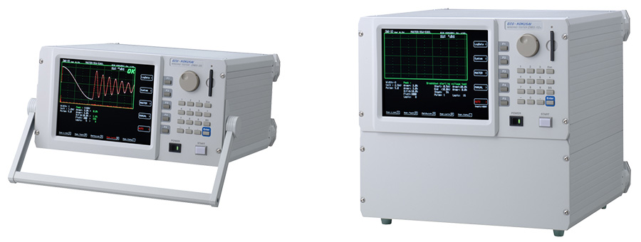
The impluse coil-winding tests the electrical characteristics of coil winding without damaging the sample. The prerequisite conditions for quality of a coil can be detected at just a glance. The detection is carried out when the same electric impulse by capacitor discharge is applied to the master and the test coils. The voltage dacay waveform is generated in response to the impluse, related to the Q-factor and inductance (impedance) of the coil. In this sense, the tester can detect turn & layer short, the differences in the number of turns and the matericak of the core. If high impluse voltage is applied, the poor insulation will appear as a corona of layer discharge.
1.AREA SIZE COMPARISON
This compares each area size of the master coil and the sample coil waveform in the intentionally determined zone. In Fig. 1, the area size is calculated between 'a' and 'b', and OK/NG(Pass/Fail) is determined by comparing the area size(i.e. what percent (%) the sample waveform's area size differs from that of the master waveform). The detecting criterion is set by %. When the result is within the set value in %, the test coil is considered to be "OK". The area size of the wave is nearly proportional to the energy loss in the coil; therefor, the test coil is considered to be OK/NG by the amount of its energy loss. For example, when a sample coil layer has a short circuit, the short circuit area is reflected as an increase of energy loss.
2.DIFFERENTIAL AREA COMPARISON
This calculates the area size of differential portion between the master coil and the sample coil waveforms in the intentionally determined zone. In Fig. 2, the differential area size is calculated between 'a' and 'b', and OK/NG is judged by detecting how large the differential area size is. The detecting criterion is set by %. When the result is within the set value in %, it is considered to be "OK". The differential area size represents the L value and total energy loss. This method is especially effective, for example, when the change of the L value causes major problems.
3.CORONA DISCHARGE (FLUTTER VALUE) DETECTION
Regardless of the difference in waveforms, this method only detects the high frequency energy of corona discharge as shown in Fig. 3. I detects the corona value in the intentionally determined zone of the waveform, and judges OK/NG by the corona evaluation value. The detecting criterion is set by an integer. The result that appears within the range is considered to be "OK". The wave is converted by derivative calculation and its area size is calculated. In an e quivalent analog circuit, the energy value of the wave that passes through high pass filter is measured.
4.CORONA DISCHARGE (LAPLACIAN VALUE) DETECTION
The Laplacian is a method in digital filter processing used for detecting the edge intensity of an image. In the application to the Flutter Value, it measures the 2nd derivative of the image to find and extract the partial discharge. The discontinuity of the value hidden in the wave data (noise) can be digitized, offering an easier detection of the partial discharge (Fig. 4).
5.VISUAL COMPARISON
The superimposed master and sample waves are displayed on the screen. This allows an easy observation of the differences in characteristics of the two coils.