
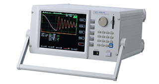
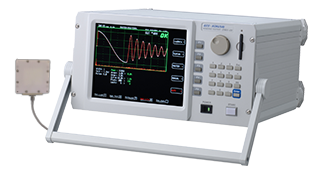
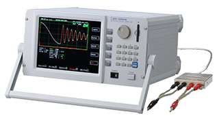
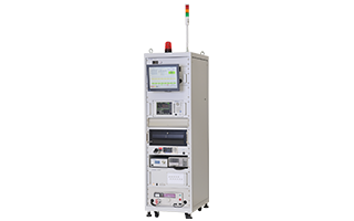

Discharge testing machine

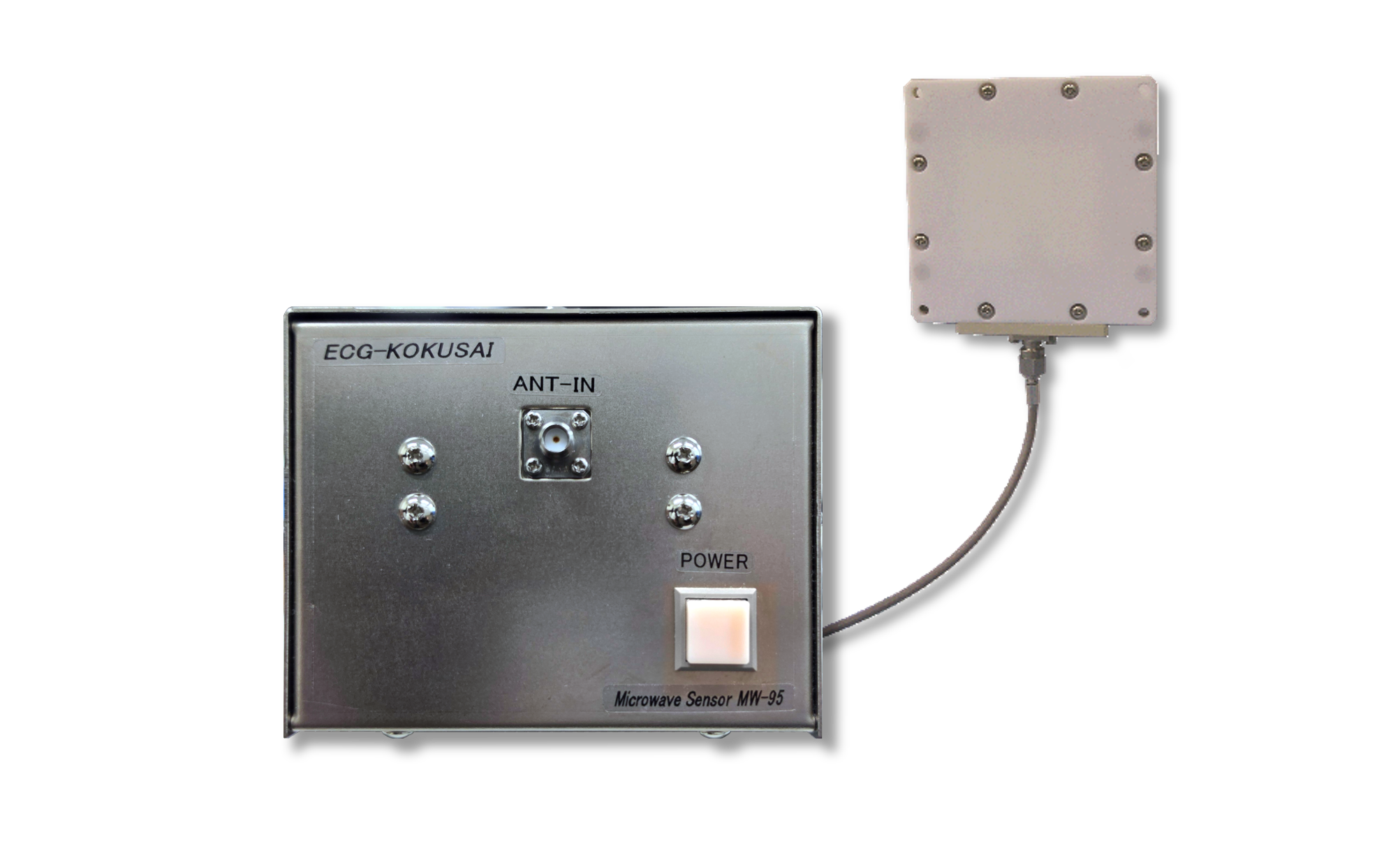
Partial Discharge Sensor

MW-95

Direct to Oscilloscope / BNC Analog Output

The MW-95 captures the electromagnetic waves emitted by partial discharge using a narrow-band microwave antenna and outputs an analog voltage via BNC. Simply connect it to an oscilloscope to monitor partial discharge with ease.

Key Strengths

Non-contact
PATCH ANTENNA
Narrow-band
1.6 GHz MICROWAVE
Sensitive
–90 to –30 dBm
BNC OUT
ANALOG VOLTAGE

Features

  • High Sensitivity Detects the electromagnetic waves of partial discharge with high sensitivity using a narrow-band microwave patch antenna.
  • Straight to Your Scope Outputs an analog voltage via BNC, so you can observe discharge waveforms on your own oscilloscope.
  • Simple Setup AC-adapter powered with no line frequency required. Easy to integrate into your own equipment.
System Configuration

System Configuration

SYSTEM CONFIGURATION
Test object Motor / Coil Patch antenna SMA 2m MW-95 Sensor amp unit AC adapter AC100V BNC 2m Oscilloscope (1 MΩ input)

Components

1 Patch antenna (MW-9A5)× 1
2 Microwave sensor amplifier unit (MW-95)× 1
3 Antenna–amplifier cable (SMA both ends, 2 m) × 1
4 Signal output cable (BNC tip, 2 m) × 1
5 AC adapter (AC100 V in / DC12 V out) × 1

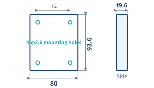
Dimensions (Antenna)

Output Signal

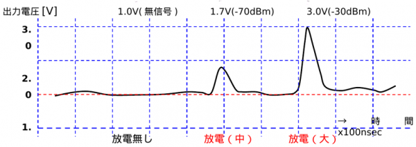
Output Signal Levels (Example)

The analog output voltage rises with discharge magnitude
— approx. 1.0 V at no-signal and up to approx. 3.0 V (−30 dBm) at PD detection.


Applications

For partial discharge (PD) detection and insulation evaluation of virtually any insulation. Ideal for stator coils/windings of EV and industrial motors, transformers, reactors and inverter-driven equipment — PD monitoring under impulse/AC excitation and as an embedded sensor in various equipment.


Specifications

ModelMW-95 (Sensor amp: MW-9503A / Patch antenna: MW-9A503A)
Detection methodNarrow-band microwave patch antenna (electromagnetic-wave sensing)
Center frequency1.6 GHz
Output signalAnalog voltage (BNC connector)
Load impedance1 MΩ or higher
Output voltageApprox. 1.0 V (no signal) to max. approx. 3.0 V (1.0±0.06 V - 3.0±0.06 V / noRF - −30 dBm @1.6 GHz)
I/O characteristic (ex.)1.0 V (no signal) / 1.7 V (−70 dBm) / 3.0 V (−30 dBm)
PowerTemperature 5-40 ℃ / Humidity 10-75 %RH (no condensation)
EnvironmentTemperature 5-40 ℃ / Humidity 10-75 %RH (no condensation)
DimensionsSensor amp unit: approx. W80 × H100 × D160 mm / Patch antenna: approx. 80 × 80 × t9.6 mm
CablesAntenna–amp: SMA both ends, 2 m / Signal output: BNC tip, 2 m
  • Model
    MW-95 (Sensor amp: MW-9503A / Patch antenna: MW-9A503A)
  • Detection method
    Narrow-band microwave patch antenna (electromagnetic-wave sensing)
  • Center frequency
    1.6 GHz
  • Output signal
    Analog voltage (BNC connector)
  • Load impedance
    1 MΩ or higher
  • Output voltage
    Approx. 1.0 V (no signal) to max. approx. 3.0 V (1.0±0.06 V - 3.0±0.06 V / noRF - −30 dBm @1.6 GHz)
  • I/O characteristic (ex.)
    1.0 V (no signal) / 1.7 V (−70 dBm) / 3.0 V (−30 dBm)
  • Power
    Temperature 5-40 ℃ / Humidity 10-75 %RH (no condensation)
  • Environment
    Temperature 5-40 ℃ / Humidity 10-75 %RH (no condensation)
  • Dimensions
    Sensor amp unit: approx. W80 × H100 × D160 mm / Patch antenna: approx. 80 × 80 × t9.6 mm
  • Cables
    Antenna–amp: SMA both ends, 2 m / Signal output: BNC tip, 2 m
AI Q&A AI Q&A