
Coil tester
Impulse Winding Tester DWX Series
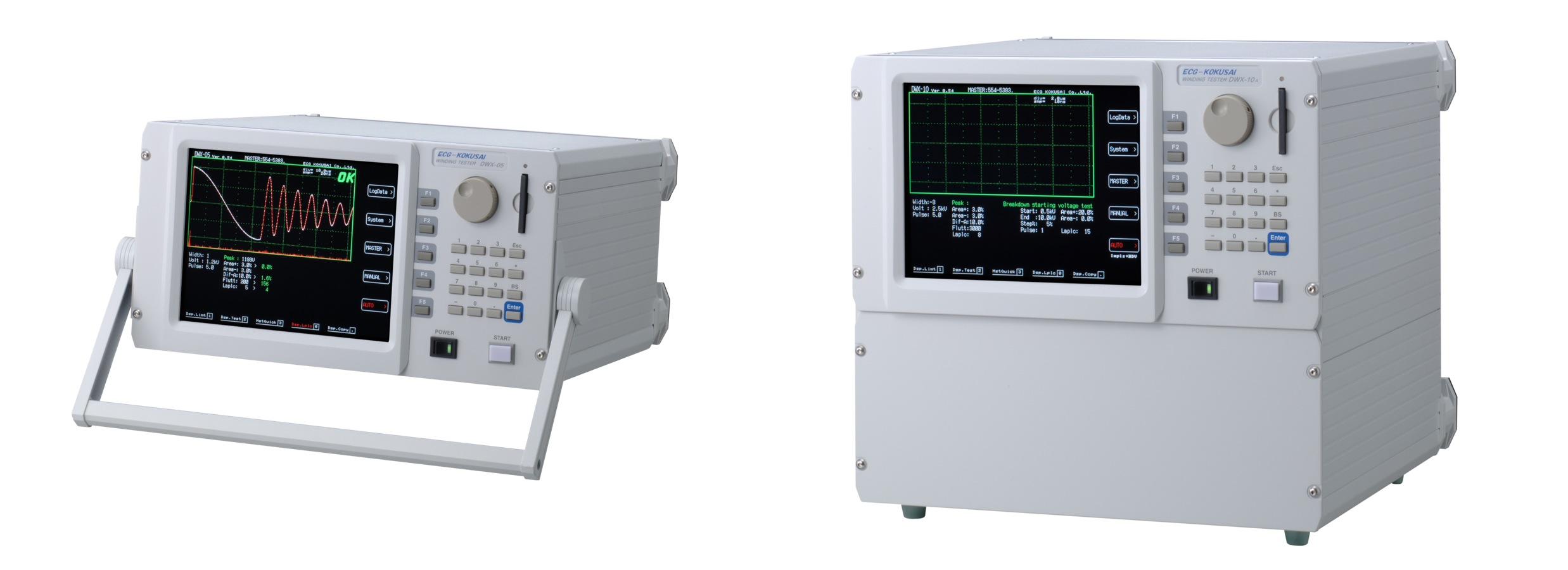
DWX-01A (1000V) - 05A (5000V) - 10A(10000V)
Definitive low inductance coil test!
Clear waveform display of 10μH coil
With the advance requirement of miniaturization and high frequency technology of coil products, the DWX tester is designed to test other coils and low inductance coils used in high end electronic components . Through the use of impulse power source with high speed switch , highly efficient input circuit, and high speed A/D sampling circuit, the DWX tester can offer a new solution to the low inductance coil tests.
DWX Series Features
This innovative tester offers a news solution for low inductance coil test.
With the advanced requirement of miniaturization and high frequency technology of coil production, the DWX tester is designed to test other coils and low inductance coils used in high-end electronic components. Through the use of impulse power source with high-speed switch, highly efficient input circuit, and high-speed A/D sampling circuit, the DWX tester can offer a new solution to the low inductance coil tests.
Its advanced technology allows a complete waveform and partial discharge observation by the resistive voltage divider.
The high performance voltage divider allows the DWX input circuit of impulse waveform to generate a complete wave pattern without any distortion. At the same time, it also helps improve the partial discharge sensitivity and detection capability
(The DWX's detection sensitivity is improved compared with that of our DW & DWS series, except for the DW-9505F).
Its high sampling rate of 100 MHz delivers highly sensitive and precise test.
Its high-speed A/D sampling helps to verify the extremely short impulse response of the low inductance coil. At the same time, the 8 kByte sampling, with highly refined data analysis, can precisely capture the subtle difference in the wave patterns.
The partial discharge amount calculated by the Laplacian method is displayed clearly in a separate sub-window.
The employed Laplacian method calculates the partial discharge (PD) generated by high voltage impulse. This PD, abstracted from the voltage wave, visually displays a bar graph in a separate sub-window, offering an easy and comfortable viewing.
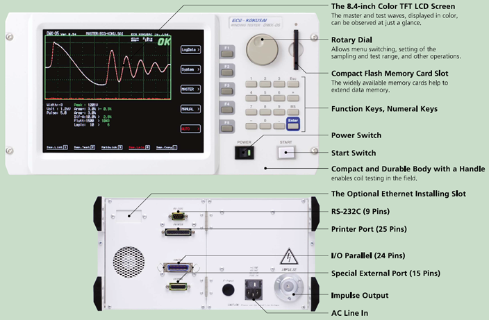
The 8.4-inch color TFT LCD screen clearly displays the waveform and is easy to view.
A combination of our proven Area, Dif-Area and Flutter comparison methods can be selected to perform the layer short test.
All types of coils can ve evaluated by choosing a combination of various test mehods: Area Size Comparison, Differential Area Size Comparison, Flutter Value (Corona Discharge) Detection, and Laplacian Value and Laplacian Value (Corona Discharge) Detection. (* The Flutter Value Detection and the Laplacian Value Detection can only be selected alternatively.)
The equipped compact flash memory device offers an unlimited memory of the master data.
HOW DOES THE IMPULSE WINDIGN TESTER WORK?
The impluse coil-winding tests the electrical characteristics of coil winding without damaging the sample. The prerequisite conditions for quality of a coil can be detected at just a glance. The detection is carried out when the same electric impulse by capacitor discharge is applied to the master and the test coils. The voltage dacay waveform is generated in response to the impluse, related to the Q-factor and inductance (impedance) of the coil. In this sense, the tester can detect turn & layer short, the differences in the number of turns and the matericak of the core. If high impluse voltage is applied, the poor insulation will appear as a corona of layer discharge.
1.AREA SIZE COMPARISON
This compares each area size of the master coil and the sample coil waveform in the intentionally determined zone. In Fig. 1, the area size is calculated between 'a' and 'b', and OK/NG(Pass/Fail) is determined by comparing the area size(i.e. what percent (%) the sample waveform's area size differs from that of the master waveform). The detecting criterion is set by %. When the result is within the set value in %, the test coil is considered to be "OK". The area size of the wave is nearly proportional to the energy loss in the coil; therefor, the test coil is considered to be OK/NG by the amount of its energy loss. For example, when a sample coil layer has a short circuit, the short circuit area is reflected as an increase of energy loss.
2.DIFFERENTIAL AREA COMPARISON
This calculates the area size of differential portion between the master coil and the sample coil waveforms in the intentionally determined zone. In Fig. 2, the differential area size is calculated between 'a' and 'b', and OK/NG is judged by detecting how large the differential area size is. The detecting criterion is set by %. When the result is within the set value in %, it is considered to be "OK". The differential area size represents the L value and total energy loss. This method is especially effective, for example, when the change of the L value causes major problems.
3.CORONA DISCHARGE (FLUTTER VALUE) DETECTION
Regardless of the difference in waveforms, this method only detects the high frequency energy of corona discharge as shown in Fig. 3. I detects the corona value in the intentionally determined zone of the waveform, and judges OK/NG by the corona evaluation value. The detecting criterion is set by an integer. The result that appears within the range is considered to be "OK". The wave is converted by derivative calculation and its area size is calculated. In an e quivalent analog circuit, the energy value of the wave that passes through high pass filter is measured.
4.CORONA DISCHARGE (LAPLACIAN VALUE) DETECTION
The Laplacian is a method in digital filter processing used for detecting the edge intensity of an image. In the application to the Flutter Value, it measures the 2nd derivative of the image to find and extract the partial discharge. The discontinuity of the value hidden in the wave data (noise) can be digitized, offering an easier detection of the partial discharge (Fig. 4).
5.VISUAL COMPARISON
The superimposed master and sample waves are displayed on the screen. This allows an easy observation of the differences in characteristics of the two coils.
DWX Series Specifications
| DWX-01A | DWX-05A | DWX-10A | |
|---|---|---|---|
| Applied Voltage, Step, and Energy * At 1 kOhm Resistive Load |
50V~1000V (10V Step) Max 5 milli-Joules |
500V~5000V (100V Step) Max 0.12 Joules |
1000V~10000V (200V Step) Max 0.5 Joules |
| Inductance Test Range | More than 10μH | More than 10μH | More than 50μH |
| Sampling Speed | 8bit/10nano-sec.(100MHz) | ||
| Sampling Memory | 8192- Byte | ||
| Sampling Range | 10 Ranges: -4、-3、-2、-1、0、1、2、3、4、5 (Width 0 to 5 is the Compatible Range with the DW Series) |
||
| Input Test Circuit (Impedance) | Resistive Voltage Divider(5MOhm) | ||
| Screen Display Resolution Waveform Display Range | 640 x 480 Dots (VGA), 8.4" TFT Color LCD, 4 Color Display 512 x 256 Dots |
||
| Detection Mode | Master Waveform Comparison
Detection by Area Size Comparison, Differential Area Comparison and Corona Discharge |
||
| Master Waveform Memory | Internal Memory: 196 Types (14 Types per Page, 14 Pages) 700-Types by Compact Flash Memory (14 Types/50 Pages) |
||
| External Interface | Parallel I/O (Start, Reset, OK, NG, Busy, Master Numbers, etc.) RS-232C (Test Control, Test Data, etc.) Printer Port (Screen Hard Copy) Ethernet Adapter (Option) |
||
| Accessories | A Tester Cable (1.5m), A Power Cable (With 3P Adaptor) A Parallel I/O Connector An Instruction Manual and Inspection Record |
||
| Environmental Conditions | 0℃-40℃, AC Voltage Upon Your Request:100V/115v/220v/240V±5% | ||
| Dimension (Excluding the Handle)/ Weight | 345(W)×185(H)×370(D) Approx10Kg | 345(W)×325(H)×370(D) |
|

